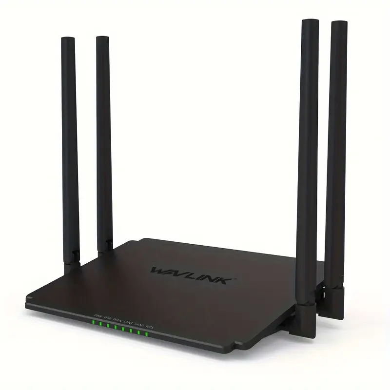
Today, I’ll be performing a teardown of the AC1200 Dual Band Wi-fi Router vM32A3_V1410_240222 and obtaining a UART shell. My goal was to explore its hardware, extract its firmware via SPI flash, and gain access to its UART debugging console for deeper analysis.
TL;DR: I dumped the device firmware off the NOR flash, identified one working UART interface out of several possible ones, soldered on pin headers, and obtained a UART shell.
Opening the Router
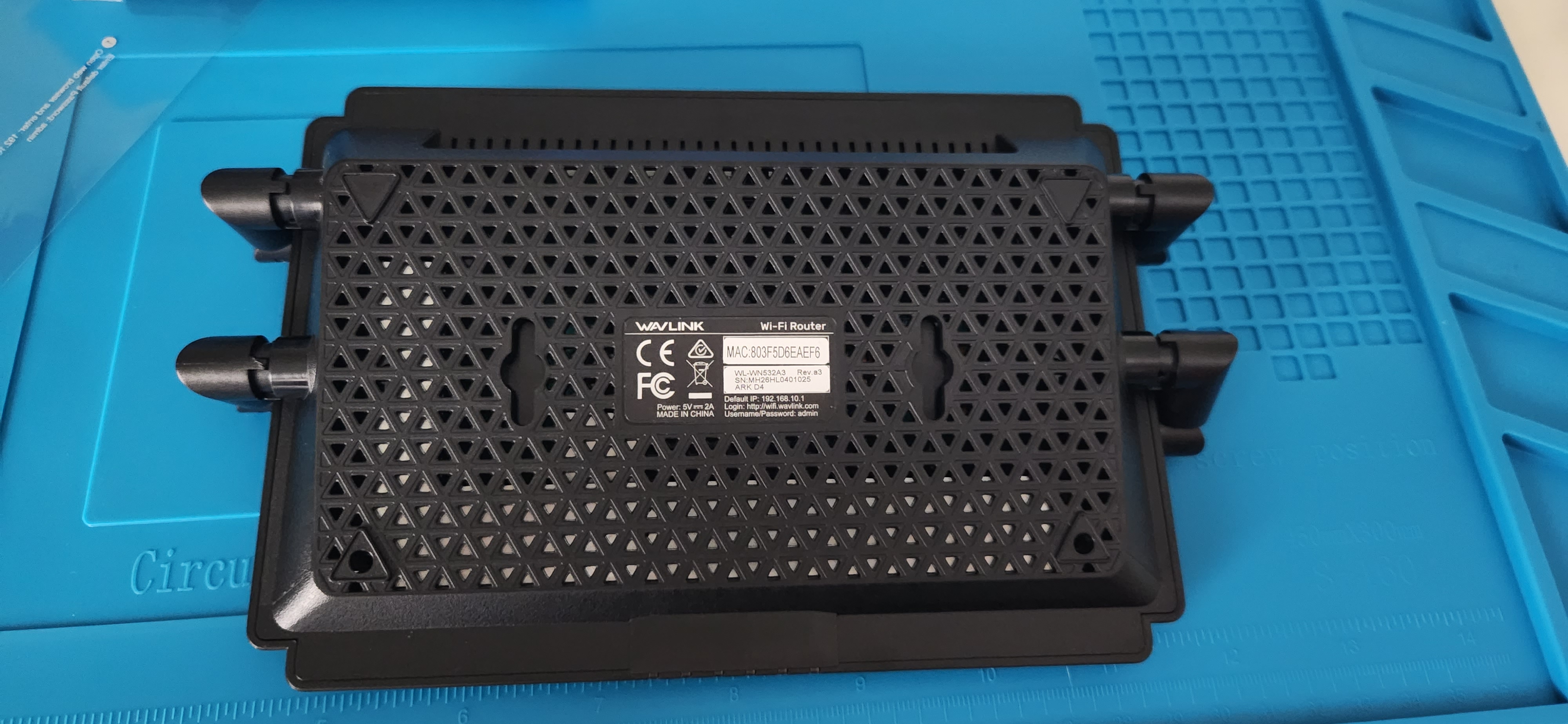
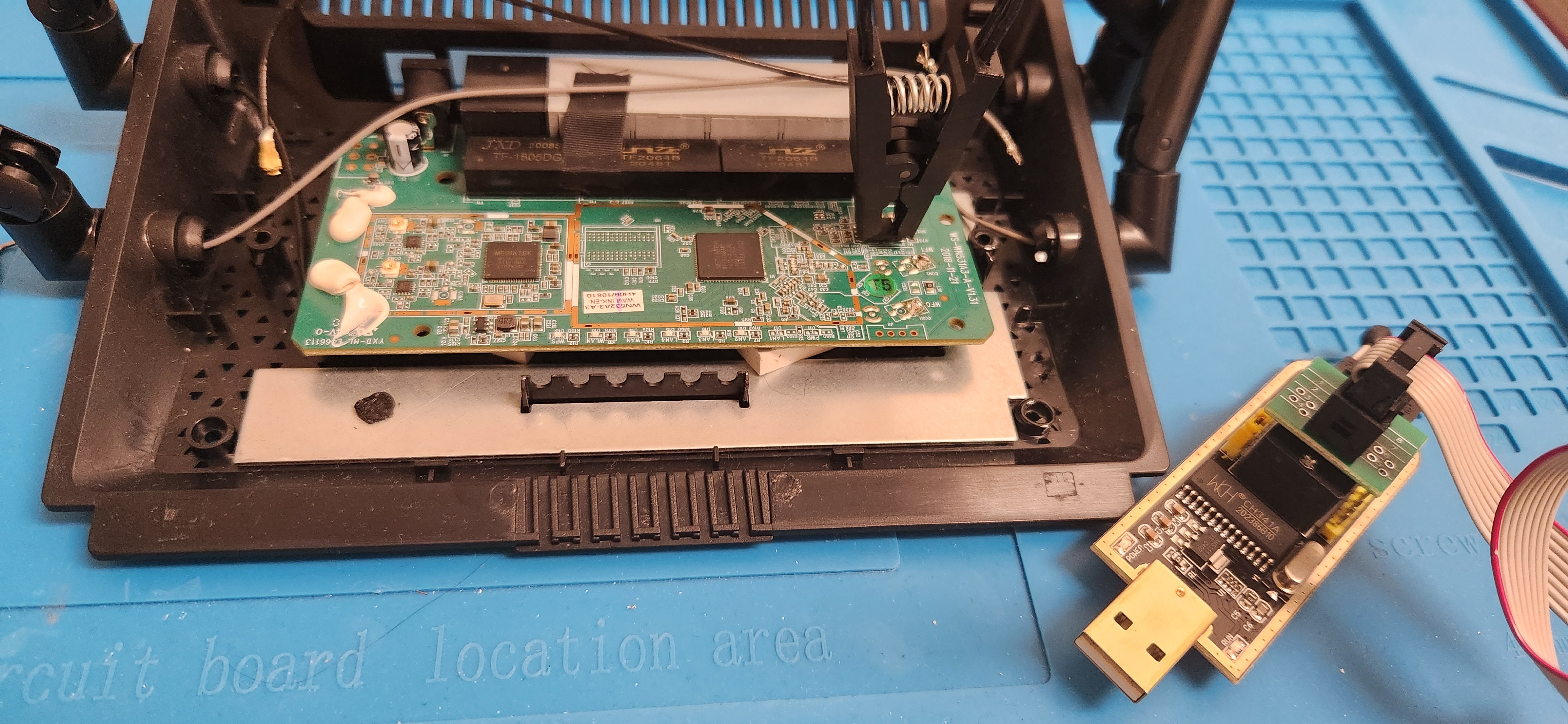
My first step was to identify the mechanisms keeping the router sealed. I found some screws hidden beneath plastic feet on the bottom of the router. I began by removing them as seen in the photo below.
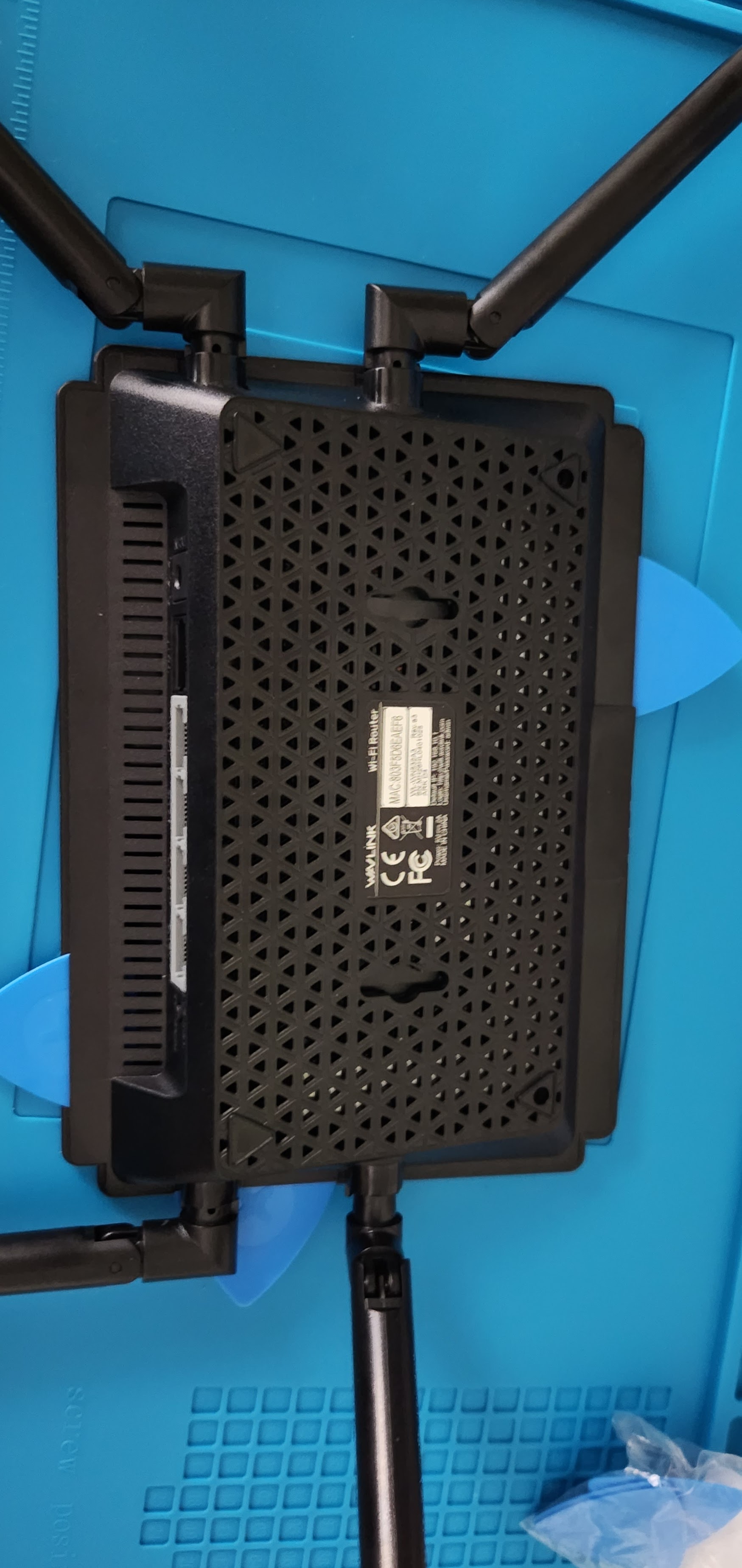
After I removed them, I still struggled to get the device open. I thought I might need to extract the antennas in case they were part of the connecting mechanism and I didn’t find online showcases of a teardown of this router.
I took a step back to recall how I opened my phone when I wanted to replace the battery 2 years ago and I remembered that I used these opening picks. I tried them again today, sliding them beneath a back panel I was able to slightly pry it open, and eventually, I heard popping noises and got a bit more access!
The picks got stuck around the LEDs on the front. I ended up applying some gentle upward force from both sides of the LED strip and attempted to slide my picks in there. This was enough to pop the back fully open.
Looking at the chips
I saw this mysterious SOIC on the board that stood out to me, however the text on it seemed to be illegible.
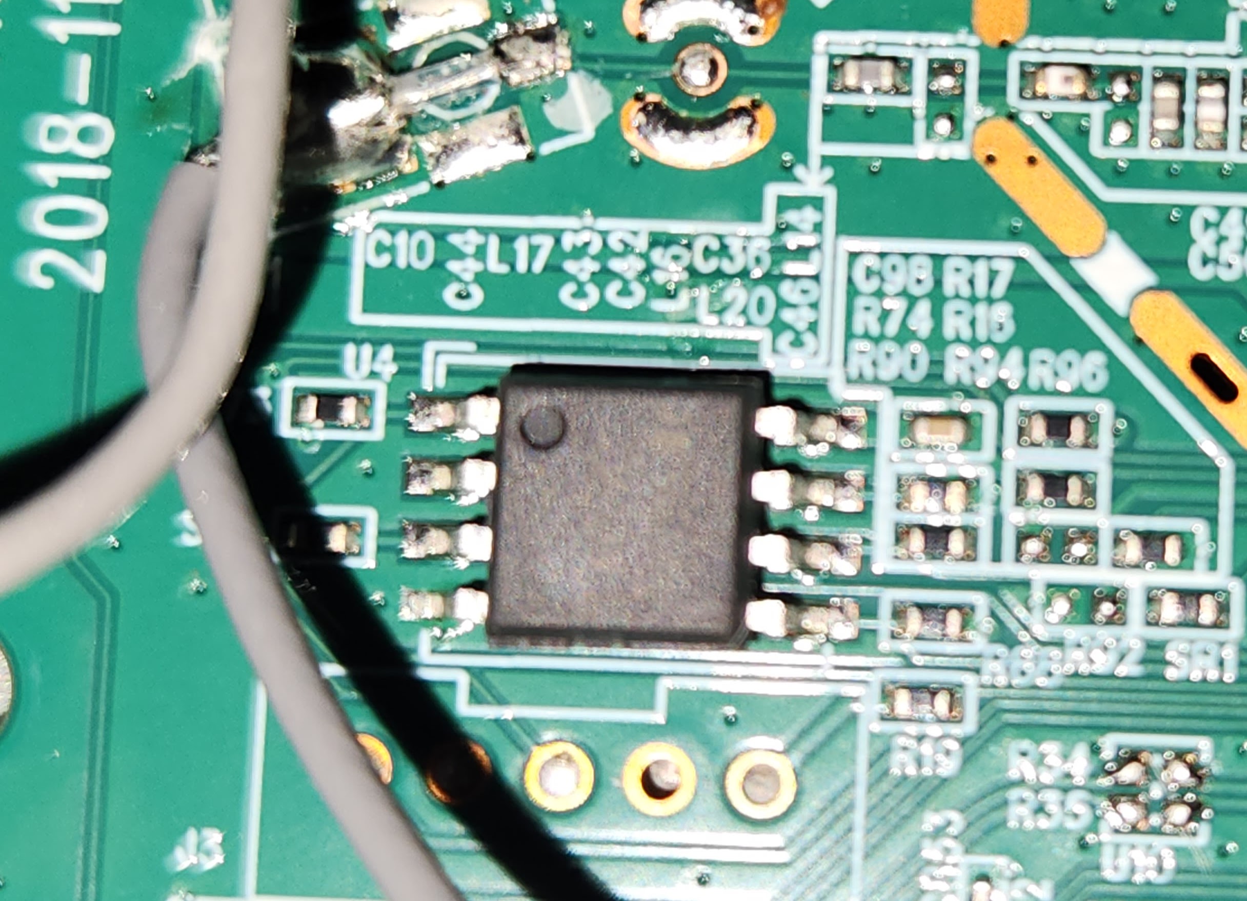
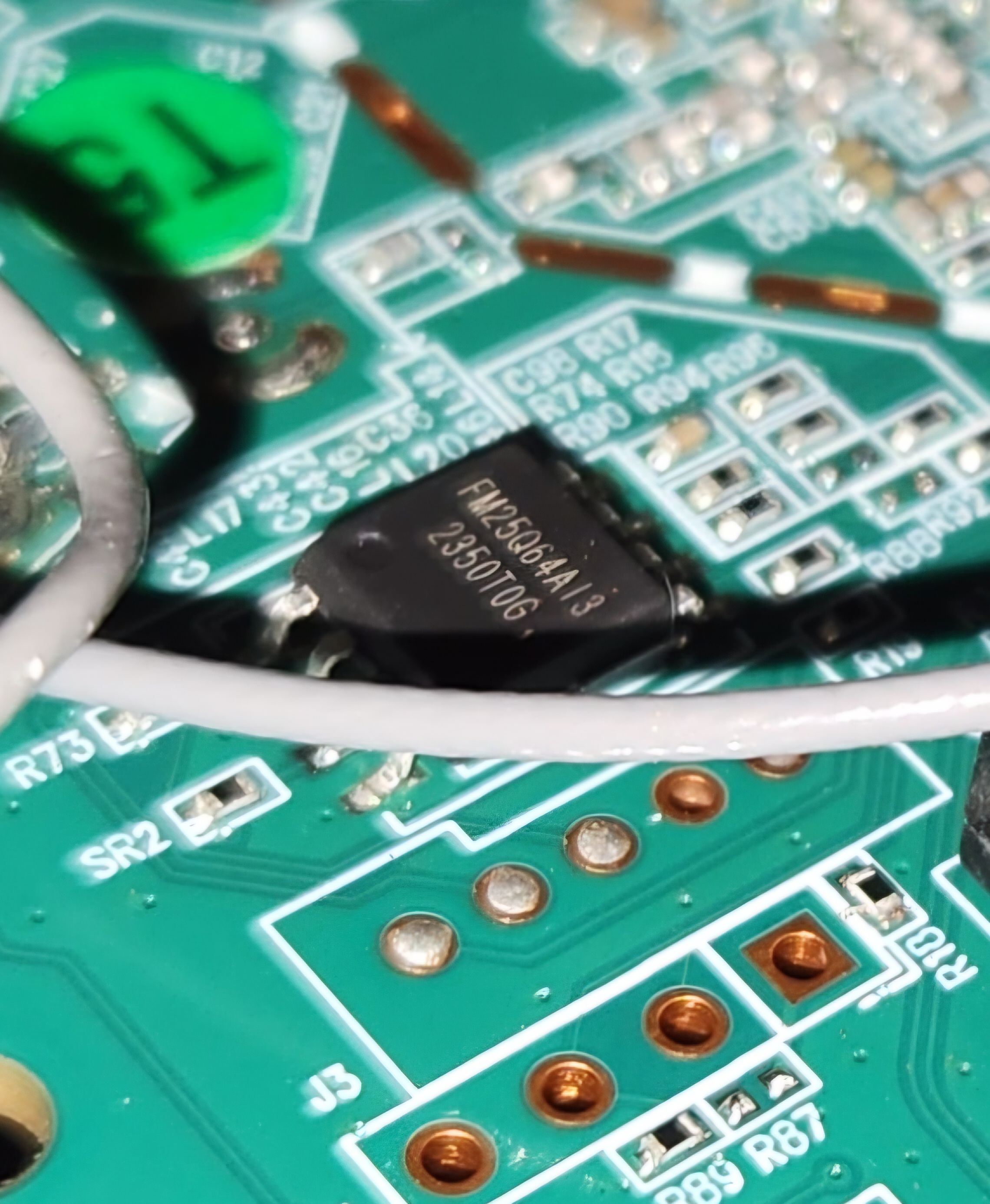
I took a tip from a Matt Brown YouTube video to shine a flashlight parallel to the chip to get a better view. But due to the constraint of only having the flashlight on my phone, I opted to instead take a picture with flash at an angle and got a much clearer read:
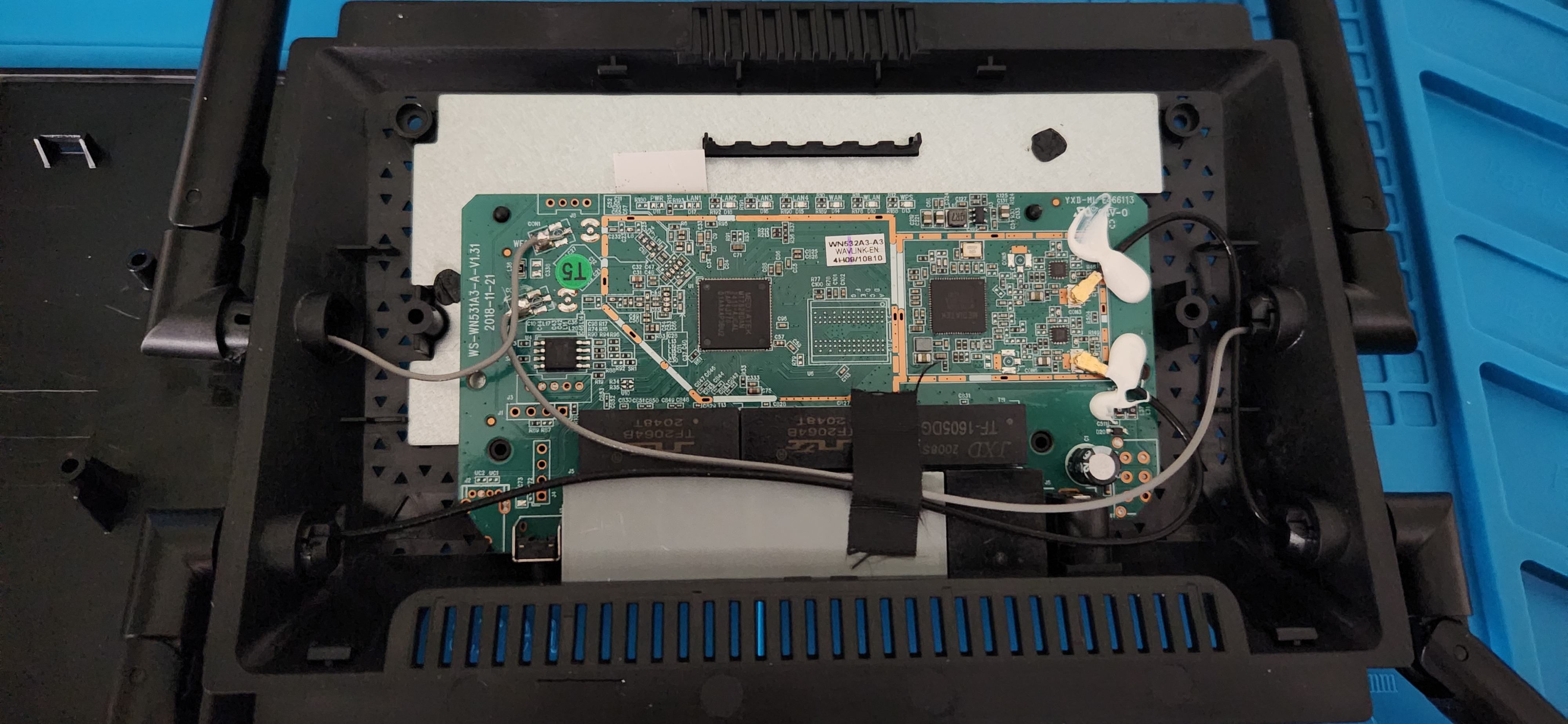
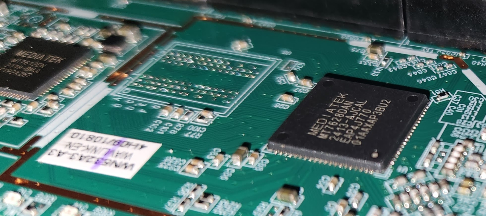
There were also some MediaTek chips on the board.
Also, I saw two of these:
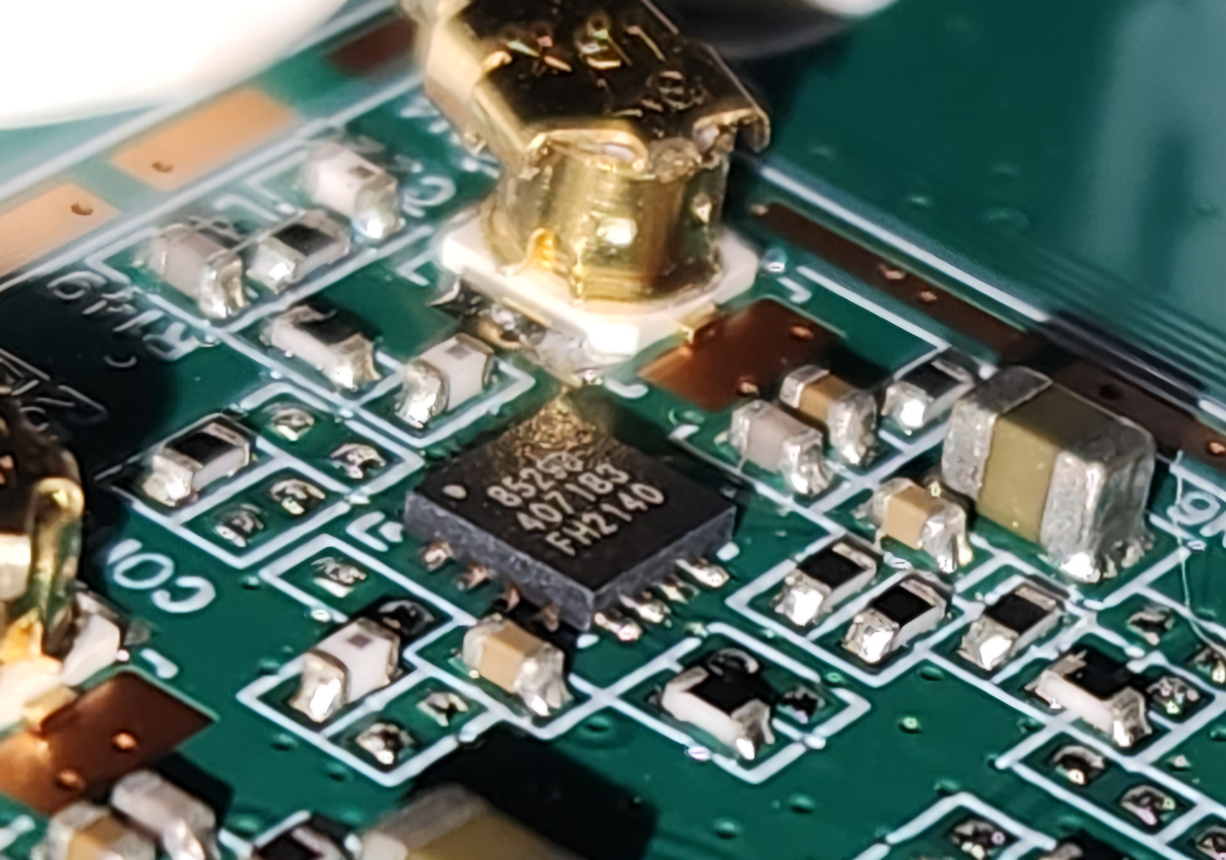
I shifted to my browser to identify what these chips may mean.
OSINT
I googled the chip names and was able to pinpoint their datasheets. The results of this search are summarized in the table below:
| Chip Name | Description | Datasheet Link |
|---|---|---|
| FM25Q64AI3 2350T0G | NOR Flash. | https://eng.fmsh.com/nvm/FM25Q64AI3_ds_eng.pdf |
| MEDIATEK MT7628DAN 2413-AJCAL EAP4J770 01AAXAP3BU2 | Router-on-a-chip with an 802.11n MAC and baseband, a 2.4 GHz radio and FEM, a 580MHzMIPS® 24K™ CPU core, a 5-port 10/100 fast ethernet switch. | https://files.seeedstudio.com/products/114992470/MT7628_datasheet.pdf |
| MEDIATEK MT7612EN 2119-BMJL ETP2X287 | Wi‑Fi single chip. | https://www.mediatek.com/products/broadband-wifi/mt7612e |
The chip that I was the most interested in was the NOR flash since it is most likely to contain the device firmware, which will help make our research more efficient. I decided to try and extract the firmware with the ch341a programmer and a SOIC8 clip.
Dumping the Firmware
This will be my first time extracting firmware from a chip. I heavily referenced this Black Hills firmware dumping article. I found the pinout of the NOR flash in its data sheet.
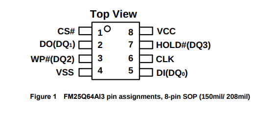
I set up the clip ensuring that pin 1 was aligned across the clip, CH341A socket, and NOR flash chip.
To properly use the ch341a for firmware extraction, I downloaded a driver from this Github Repository and launched AsProgrammer on my Windows laptop. I then selected my chip (IC > SPI > FIDELIX > FM25Q64A) and clicked the box with the arrow coming out of it to begin reading from the chip. With that, I was able to get a successful read of the firmware!
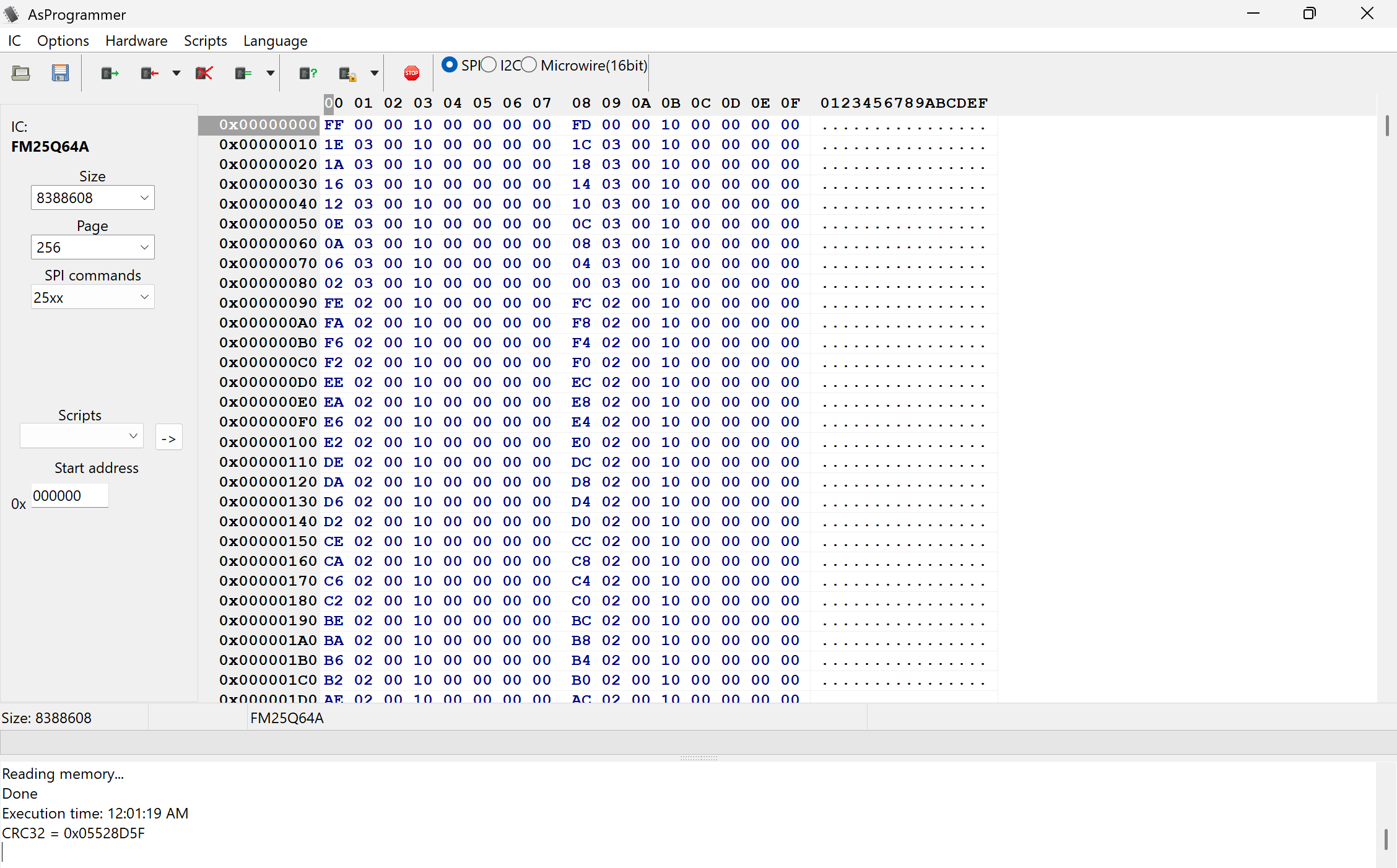
I will be doing more analysis on this firmware in part two of this blog post, but for now, we will redirect our attention to UART!
Getting Debug Access
Identifying UART Interfaces
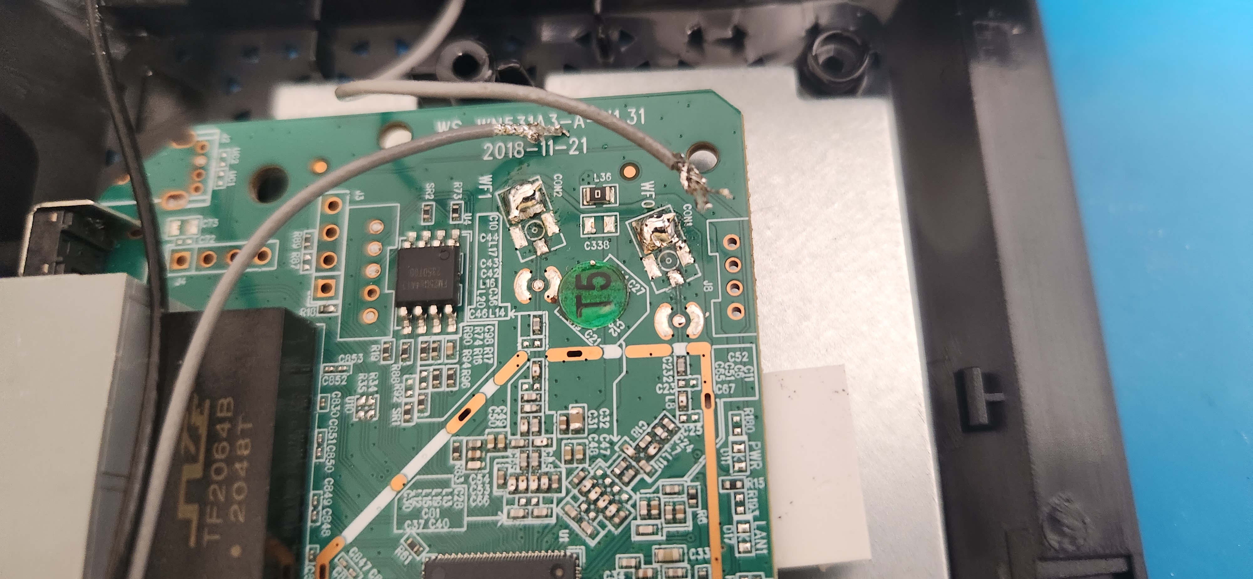
I noticed what appeared to be a series of four potential UART interfaces on the board. Maybe a fifth one if one of the through-holes on it were unused.
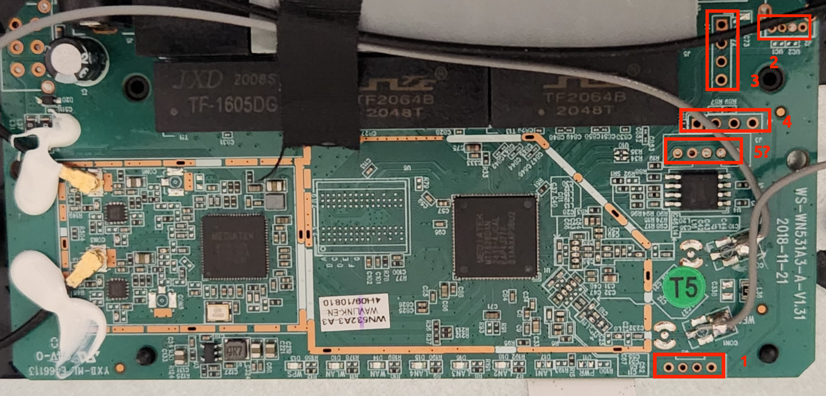
This was my first time attempting to connect to UART, so I referenced this Matt Brown video for the next steps. I ended up following this process of identifying the pinout of the UART interfaces starting with the top right vertical interface labeled 3:
- Find a ground point on the board.
- I used the brass top of one of the black cables coming from the antenna.
- Use a multimeter to check for continuity between the ground point and ports of the UART interface to identify ground.
- I found continuity with the bottom pin on the third labeled interface
- Start the router and probe the ports for fluctuating voltage (likely TX), constant voltage (likely VCC), and no voltage (likely RX).
This was where I encountered some issues. I wasn’t seeing these series of TX, VCC, and RX pins. I checked for continuity between the through hole and the CPU and there seemed to be a direct connection.
In fact, when probing around all of the five potential UART interfaces, the majority of the pads seemed to either be ground or VCC… except for a pin on the fourth interface identified that contained fluctuating voltage. It seems that we found the correct interface.
Interestingly, when I later obtained a digital logic analyzer and observed each of the connections on the 4 other potential UART interfaces, there did not appear to be any data being sent at all. Luckily for us, just one working interface was all we needed.
Further probing with a multimeter helped me to identify the following pinout from left to right:
| Pin # (starting from the left) | Label |
|---|---|
| 1 | VCC |
| 2 | GND |
| 3 | TX |
| 4 | RX |
Creating a Physical Connection to UART
I wanted to connect to these UART pins so that I could read the debugging output. I decided to put my recently-acquired soldering skills to the test and attach pin headers that I could use to interface with the plated through-hole. However, there was a problem. I couldn’t remove the PCB from the chassis with the antennas soldered onto the board to get the physical access I wanted to perform this soldering.
Attempting to desolder the antennas as-is did not seem to work as the solder would not melt with my iron’s max temperature of 480 degrees farenheit. To solve this, I melted some Sn99 Ag0.3 Cu0.7 solder onto the connections at 419 degrees and was able to get the entirety of the connecting solder to melt once a new alloy was formed.

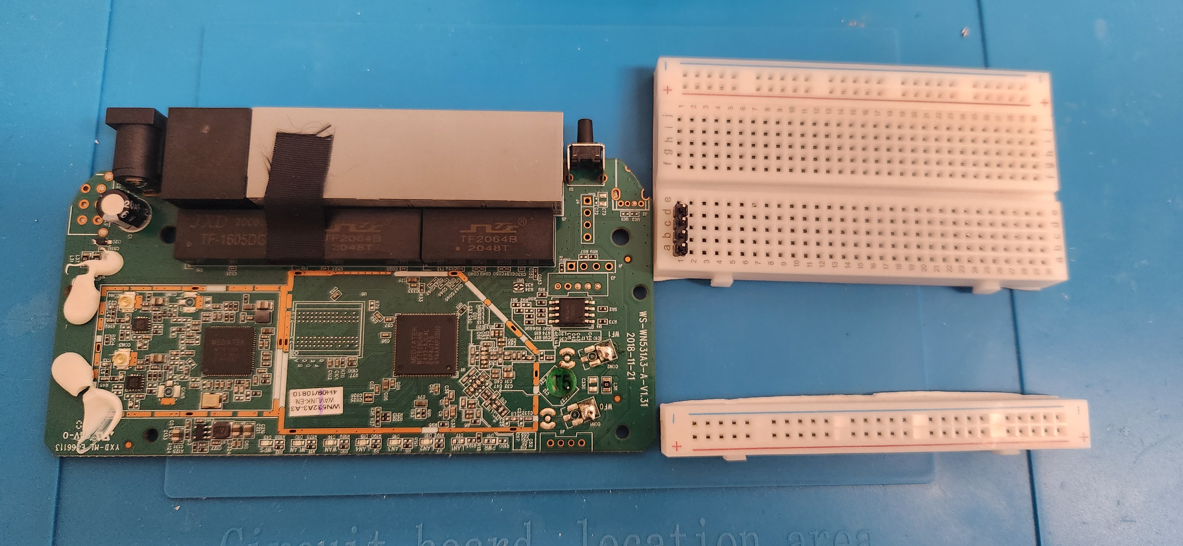
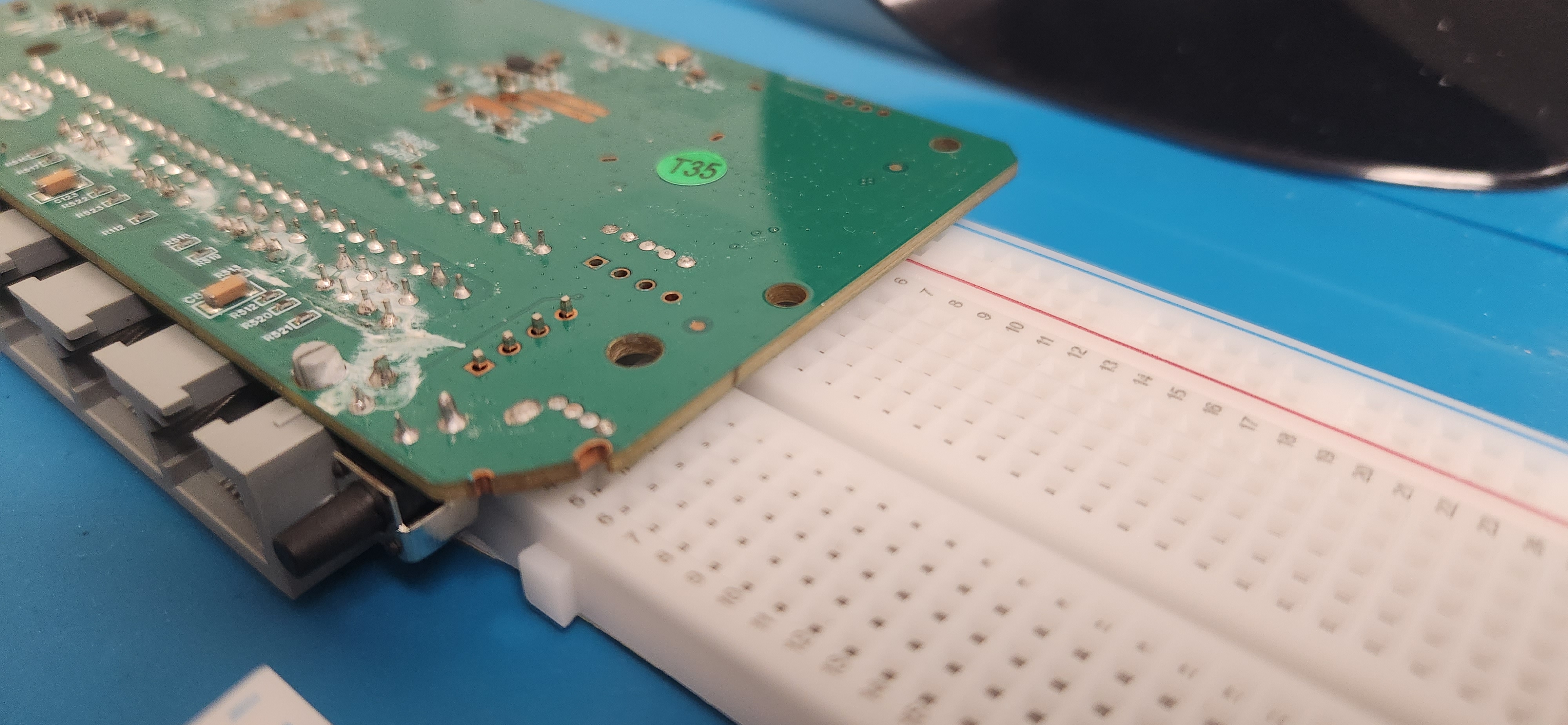
With my increased physical access, I got a strip of male pin headers, cracked off four of them, took the PCB out of the Wavlink router, and soldered them with a dev breadboard beneath as a jig to ensure stability and a straight connection. I had to break off the power strip of the breadboard I had laying around so that I could line it up with the board without hitting other components.
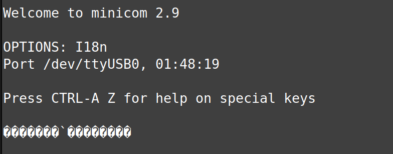
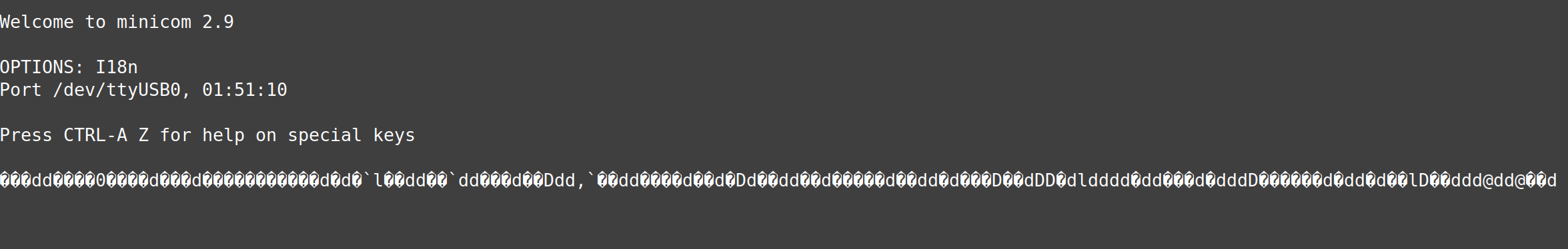
My first attempt at soldering on these pin headers was not a success. I tried reading the UART output through my shell, but got non-printable characters that seemed to come more frequently when I applied pressure on the pin headers.
I did not know what this was, so I decided to investigate.
Troubleshooting my Failed UART Connection Attempt
To view the UART output, I used this an FTDI cable and connected the TX pin I identified to the RX reciever. Then, I plugged this into my Linux machine, which verified that it is identified as ttyUSB0.
$ sudo dmesg | tail -n 30
[26610.245645] usb 1-8: Manufacturer: FTDI
[26610.245648] usb 1-8: SerialNumber: [REDACTED]
[26610.354160] usbcore: registered new interface driver usbserial_generic
[26610.354180] usbserial: USB Serial support registered for generic
[26610.356524] usbcore: registered new interface driver ftdi_sio
[26610.356542] usbserial: USB Serial support registered for FTDI USB Serial Device
[26610.356716] ftdi_sio 1-8:1.0: FTDI USB Serial Device converter detected
[26610.356769] usb 1-8: Detected FT232R
[26610.363780] usb 1-8: FTDI USB Serial Device converter now attached to ttyUSB0
[26610.693286] usb 1-9: reset high-speed USB device number 3 using xhci_hcd
-- snip --
I googled common baud rates and tried them each in screen until I found one that displayed valid ASCII characters when the router is rebooted.
A baud rate of 9600 didn’t work.
sudo minicom -b 9600 -D /dev/ttyUSB0
38400 was closer…
I went through all the standard baud rates and even found some online sources indicating that other Wavlink routers have had a baud rate of 57600, however that did not seem to work on mine.
At this point, I decided to look through my extracted firmware to see if I could find any references to the baud rate in the code.
remnux@remnux:~/Documents/wavlink-ac1200/_wavlink-ac1200.bin.extracted/_50040.extracted/_52D000.extracted/cpio-root$ rg -i --binary 'baud'
Binary file bin/pppd matches (found "\u{0}" byte around offset 7)

Binary file bin/comgt matches (found "\u{0}" byte around offset 7)
remnux@remnux:~/Documents/wavlink-ac1200/_wavlink-ac1200.bin.extracted/_50040.extracted/_52D000.extracted/cpio-root$ strings bin/comgt | grep -i baud
baud
Invalid baudrate
remnux@remnux:~/Documents/wavlink-ac1200/_wavlink-ac1200.bin.extracted/_50040.extracted/_52D000.extracted/cpio-root$ strings bin/pppd | grep -i baud
baud_rate
	<speed>		Set the baud rate to <speed>
Baud rate for %s is 0; need explicit baud rate
Baud rate for serial port
I did end up finding some references as seen above. bin/comgt seemed like the most promising binary to me since the Invalid baudrate string in it indicated that it was performing a validation on the baud rate. If this was the case, we may be able to find what the expected baud rate is!
I tracked down the string in ghidra and found these checks implying that valid baud rates are 57600 and 38400.
                            if (iVar6 != 57600) {
                                if (iVar6 < 57601) {
                                    if (iVar6 != 38400) {
                                        FUN_00402994("Invalid baudrate",1);
                                    }
                                    DAT_0041d228 = 0xf;
                                    goto LAB_00405b70;
                                }
Trying 38400 didn’t seem to work either, however this discovery gave me confidence that an invalid baud rate was not the problem. This baud rate is consistent with other Wavlink models as seen in this writeup. The order of the UART pins also appeared to be the same but in reverse.
The next question that came to me was “Could my soldering connection be incomplete leading to data getting lost?”
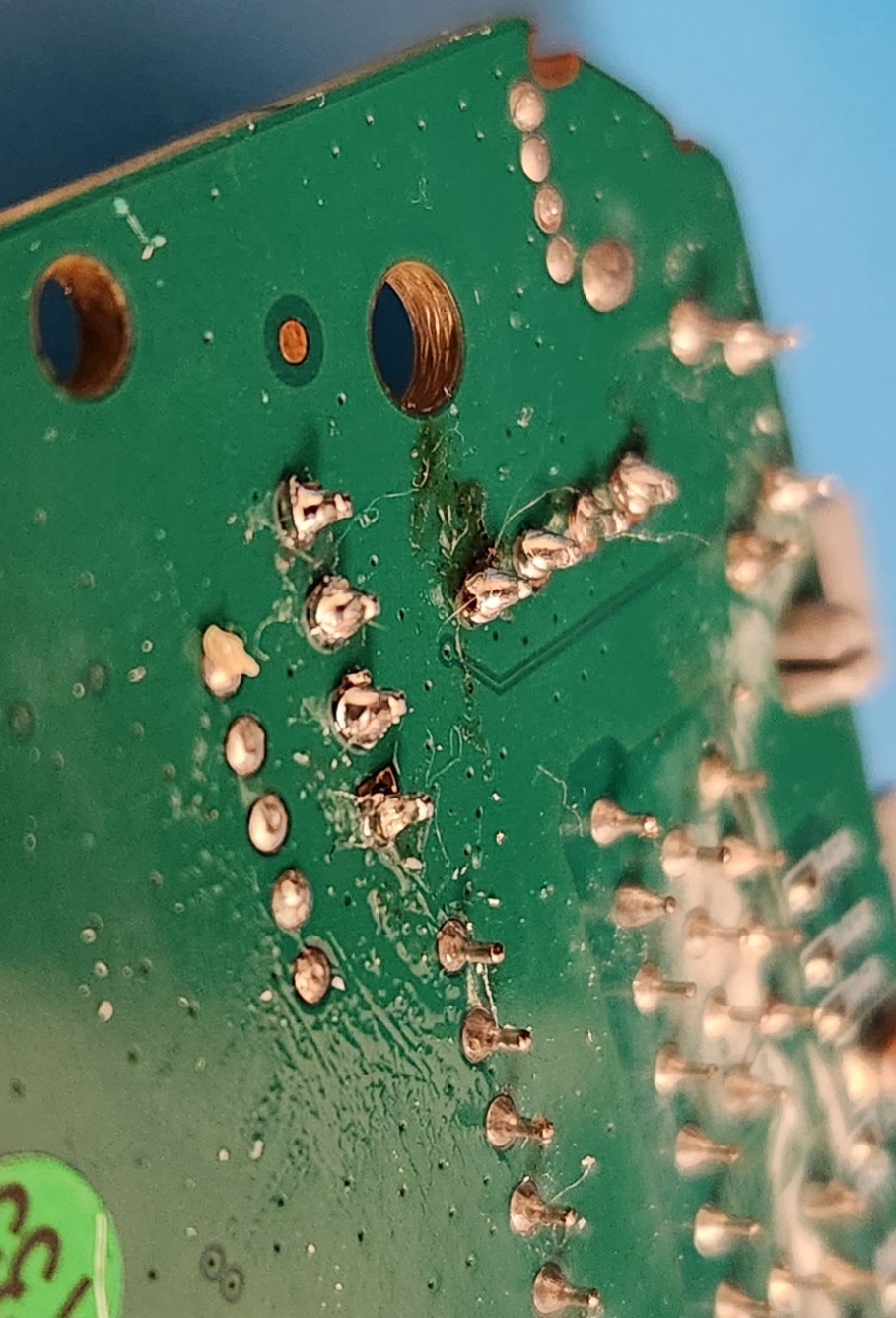
I started poking around the pin headers and found that I was able to wiggle them from left to right with very little resistance. The solder didn’t seem to properly bind between the copper lining the through-holes on the board and the pin. While soldering, the solder seemed to stick to the iron rather than the copper.
Furthermore, I found that applying pressure to the pin headers while attempting to read through the UART console would create a burst of data on screen. These signs indicated to me that my initial soldering job was incomplete, which must have caused data loss and invalid output.
Fixing the UART Connection
I was able to fix this by doing the following in my next soldering attempt:
- Switching my solder alloy to 63% tin and 37% lead
- Changing the iron temperature to 380 degrees farenheit
- Cleaning the copper interfaces around the uart holes with 91% isopropyl alcohol to remove some oxidation on the surface and help with binding
- Paying closer attention to my technique ensuring that the copper pad is getting enough heat
- Adding additional flux when needed
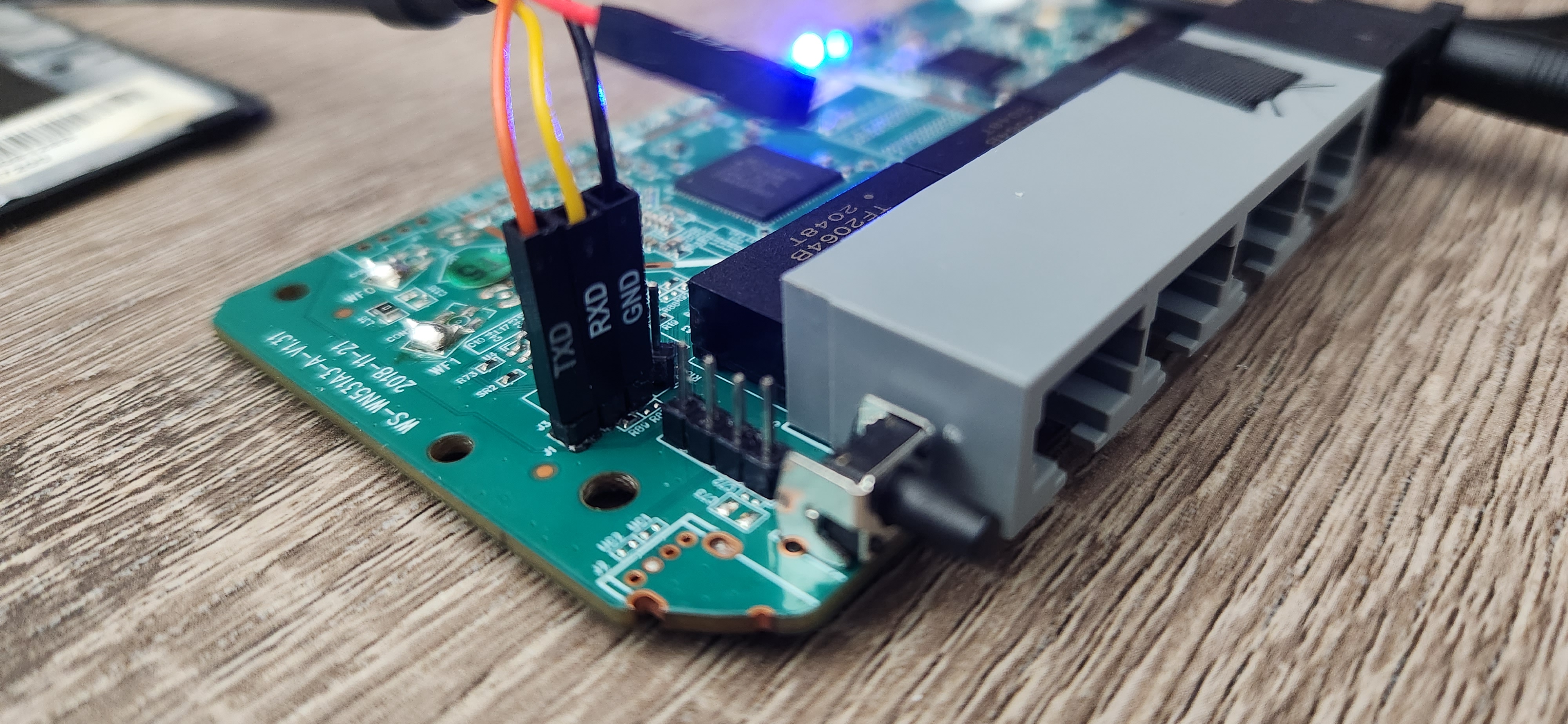
I finally got it!
It may not be the prettiest solder job, but it accomplishes what it needs to. All that is left is to connect the female jumper cables from my FTDI cable to the pin headers I had just soldered on and start reading!
Interpretting the Boot Logs
The full boot logs can be found on my GitHub here. It has network interface errors due to the detached antennas from the soldering step.
Here are some details that stood out to me when reading through these logs:
- U-Boot v1.1.3 (Jun 5, 2023)
- Ralink UBoot Version: 5.0.0.0
- There are boot options to enter the boot CLI or load a custom firmware
- Linux version 2.6.36
- firmware version build time: 201511101431 (must have been reused on top of a newer bootloader)
These lines stood out to me:
[    5.832000] [WAV_FLASH]FOUND_BY_ENC_FLASH
[    5.840000] Wavlink Encryption System is unlocked!
I am curious to learn more about their encryption implementation such as the type of data that they encrypt and how the keys are stored or generated.
Eventually there was a prompt at the bottom for login information.
WAVLINK login:
Unfortunately, I didn’t seem to be able to type any input into the UART shell to attempt a login. I verified continuity between the soldered RX pin header and the CPU with a multimeter. Despite this, it still seemed to be a readonly shell. Further investigation of this may occur in a future post, but for now, I am curious to shift my focus to the firmware.
See Part 2 for a 0-day I found on accident while trying to understand their key generation functionality.